Video Mapping, 3D Photogrammetry, Anamorphic Images, LandArt
Photogrammetry 3d, based on panoramic 360° photos, explications
Photogrammetry, definition. Automatic 3d mesh or Manual 3d modeling ?
Photogrammetry is the practice of determining the 3d geometric properties of an object from photographic images and get reliables informations about reals objects.
There is a lot of softwares that deliver automatic and textured 3d models and/or colored point cloud starting from photos.
We will not talk about those process here because automatic 3d mesh are too complex and not always effectives to use as a virtual screen in the digital video projection process.
Their texture is automatically generated so the 2d file of the texture is really not readable and useful to be used as a texture map for content creation.
Those automatic 3d meshes can be a plus to help to redraw a building but they're not crucial. They can be useful sometimes to insert some complex and "organic" details into a manually modeled building.
The video mapping screen must be modeled manually to be optimized and useful for 3d mapping simulations, content creation and to play inside the media server if needed. Some media servers have a 3d real-time engine, like the SMode by D/Labs and the Modulo KINETIC by Modulo pi.
My job is almost all about digital mapping. That's why I almost always make 3d models manually.
To acheive this process I use the spherical panoramic photos technique, that I will show you in detail in this page, staring on what is a panoramic 360° image.
Panoramic 360° image, equirectangular projection
A panoramic 360° photo is an equirectagular image. The image ratio is 2:1.
An equirectangular image is what you need to map a sphere. This process is called equirectangular projection.
The most common equirectangular image is the earth map. Below you can see an earth map on the left and the same image used as texture projected on a sphere inside a 3d software :
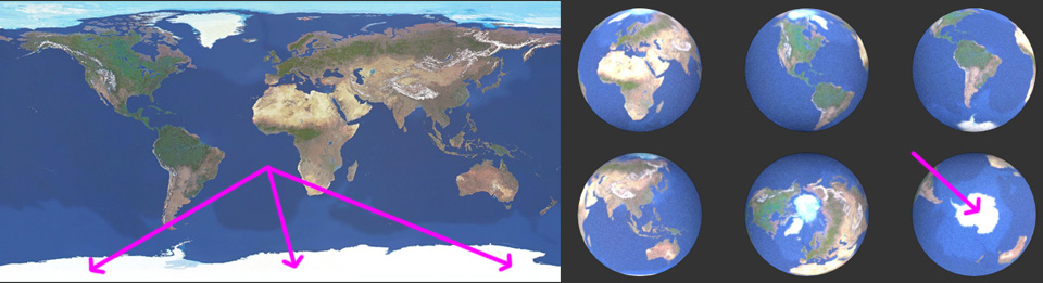
Note the different size between the poles areas represented on the equirectangular image compared to their sizes once projected into the sphere
Photogrammetry Process Step 1 - go on site and take panoramic photos and measurements
The first step is to go on site and take some panoramic photos, detail photos and measurement.
Very useful is to get as much informations as possible about the venue, such as autocad or pdf files and/or 3d models that may already exist.
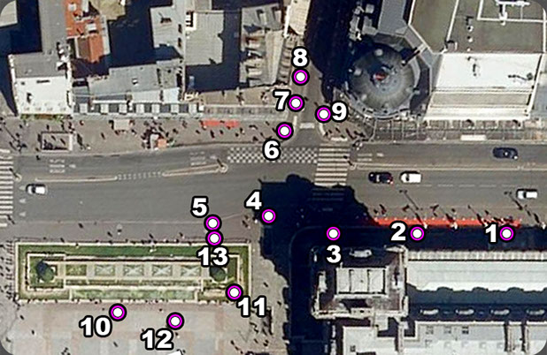
On the left you can see the locations where I took panoramic 360° photos.
If the purpose of the project is video mapping you may not forgot to take panoramic pictures from the audience point of view, VIP point of view and video projection point of view. In this case photos number 10 is the main audience point of view, number 13 is the VIP point of view and number 12 is the video projection location (useful also to get the best texture for the final 3d model).
You can click the thumbnail below to open the full screen panoramic photo as an example.
Inside the full screen panoramic photo you can navigate and look around by simply click and drag. You can also change the zoom value using the mouse wheel or SHIFT and CTRL on your keyboard.
Below you can see how it look the flat equirectagular photo.
The original size of one panoramic photo is 24576x12288 pixels, more than 3 hundred mega pixels ! You can click here or in the image below to download the zipped original photos (156 Mb).
")
Each panoramic photo is a stitch from 26 normal photos taken with a full frame photo camera, a 24mm lens, mounted on a panoramic head and a sturdy stable tripod. I take 12 photos each 30° of rotation looking up, 12 photos each 30° of rotation looking down, one photo all the way up (zenith) and one photo all the way down (nadir).
Photogrammetry Process Step 2 - stitching all panoramic photos and put them into a 3d virtual environment
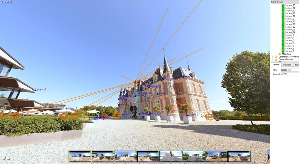
Once all panoramic photos are stitched it is time to put them into a 3d virtual environment. To explain you that phase here you are an example of the "Château de Chantilly" near Paris. For this project I use 8 panoramic photos.
Inside Image Modeler, I start to put points on the building (those point are called "locators" inside the software) that are seen from different photos. I have to put the right location of each point seen from each panoramic photo. This process is called "calibration". Once there is enough point to calibrate all the photos the software is able to place into the 3d environment the location where the photos was taken.
Those points are like a custom cloud point that I choose on the building and that help me to build the model.
In the photo below one point is selected. This point is "locator 24". You can see the locations where I stop to take photos on site, symbolized by wire-frame orange spheres.
From those spheres to the selected point you can see an orange line : this means that the selected point is correctly seen and calibrated by all the panoramic images. Note that the residual error is 0.33 pixels. If you consider the size of a panoramic photo, 0.33 pixel is really nothing !
Before exporting the project there are two more things to do : define the origin and the orientation of X, Y and Z, and enter a distance between two "locators" to put everything in scale.
Now that the calibration process is done it is time to export the 3d scene and start the modeling of the building.
Photogrammetry Process Step 3 - importing the 3d file into your preferred 3d software
When you import the 3d files from Image Modeler all you have in the scene is one camera for each panoramic photos and a point cloud composed by red dots. All those points are named exactly as they were into Image Modeler.
Before doing anything I have to create a sphere aligned to each camera and map those spheres with the correspondent panoramic photo. Note that the mapping is from the inside (and not from the outside like the world map at the top of this page), so I have to reverse the tiling of each photos.
Also, all cameras came with some rotation values. I have to apply the inverse rotation value of the camera to the correspondent sphere to align everything.
To see the cloud point trough the cameras I have to slow down a little bit the opacity of each sphere.
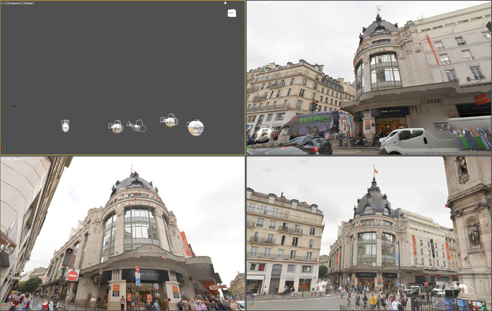
Below you can see a screen shot inside the 3d software. The workspace is divided into 4 windows. In the top left windows you can see some cameras inside their sheperes and the point cloud composed by red dots while the other 3 viewports are in camera camera view.
Photogrammetry Process Step 4 - manual 3d modeling
I can now start the 3d modeling process. This is the part that I prefer ;-)
The concept is easy to understand : if one object is at the same place when I see it from all the photogrammetric cameras this means that is in the right place. The error is less than one centimeter and is not cumulative but compensated.
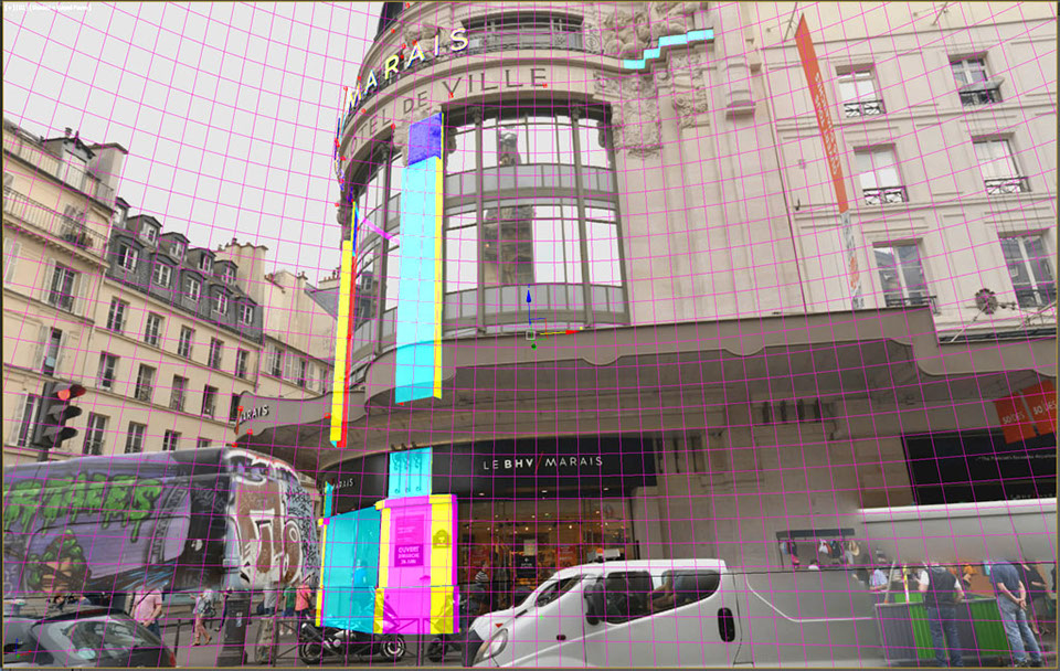
When I model looking trough the transparency of each spheres I use to apply full colors to the model so that I can easily see what I am doing.
So, 100% red, blue and green + cyan, yellow and magenta.
I use to call this method of 3d modeling a "no control z modeling" because I always implement the model and go further without any possible doubts.
Finally here you are a video from my vimeo channel that show you a time-laps of the 3d modeling of the DrugStore Paris Champs Elysées.
The building is almost all made by glass surfaces so quite impossible to be scanned with a laser. Photogrammetry is here the best choice !
In the 3d view-port I use to draw in the top left window and see trough the photogrammetry cameras in the other 3 window.
If you find this page helpful please like it below or leave me a message or a comment via the contact form.
See all my mapping, photogrammetry and 3d design videos on Ugo Cassanello's Vimeo page
Follow UGOsansH on FaceBook www.facebook.com/video.mapping.photogrammetry
Access to Ugo Cassanello's YouTube channel dedicated to digital video mapping and photogrammetry
Want to leave me a message ? You can use the form in the contact page